Some UPDM Views can be represented by UML based diagrams. The DoDAF module provides a set of diagrams specific to UPDM views. Each diagram has its own Palette dedicated to a specific View.
Create a diagram specific to a UPDM view
Right-click on a UPDM view and select Create a diagram or a matrix… 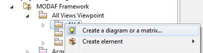
A diagram creation wizard opens. In the Type selection browser, there is a set of diagrams structured in contexts. The UPDM available diagrams are accessible on the DoDAF entry (diagrams specific to the DoDAF context). By default, a filter is applied so only the diagrams specific to a view are available. It is possible to show other diagrams by clicking on the Show only applicable diagrams and matrices.
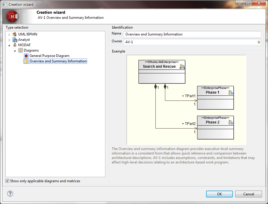
Please note that a General Purpose Diagram is available on all Views. It allows to represent any element (in static views).
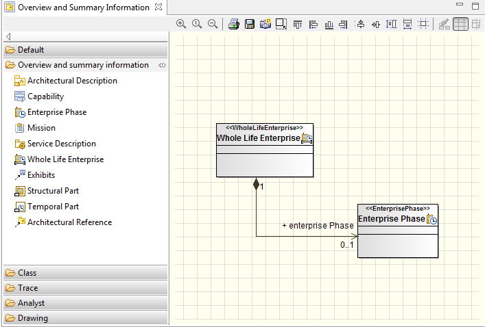
A diagram view opens.
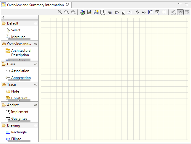
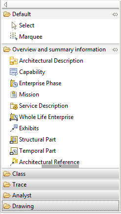
At the right of this view there is a palette of elements that can be created on the diagram. This palette is organized in set of commands. It is possible to shrink or expand a set of commands by clicking on the name of the set of commands. On the example below, we have clicked on Class, Trace, Analyst and Drawing sets of commands so we have a better visibility of the Overview and summary information commands.
To create an element on the diagram view, just click on a palette element then click inside the diagram view where you want it to appear.
When you create an element on this way, it is created on the parent UPDM View. If you need to unmask an element which is present on another UPDM View, select it from the Modelio explorer and drag&drop it to the diagram view.