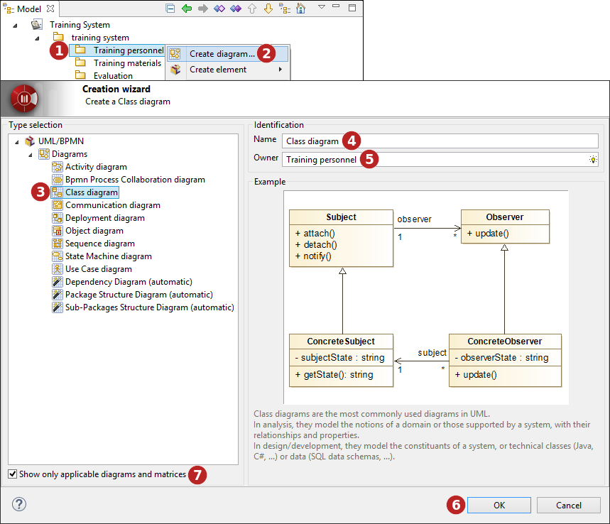
How do I create a diagram in Modelio?
-
By using the Create diagram… command from the contextual menu.
Diagram creation wizard
Keys:
-
Select the element on which you want to create a diagram.
-
Click on the "
 Create diagram…" button in the selected elements contextual menu.
 -
Select a type of diagram.
-
Enter a name for the new diagram or leave the default name.
-
If the diagram owner is different from the selected model element, indicate the diagram owner.
-
Click on "OK" to complete the new diagram creation.
-
Non-applicable diagrams are greyed and can be masked by checking the "Show only applicable diagrams" tickbox.
Diagrams supported by Modelio
As standard, Modelio supports the following types of diagram:
-
Class diagrams, which present an element’s internal structure and its relationships with other elements.
-
Composite structure diagrams, which show the internal structure of a class and the collaborations that this structure makes possible.
-
Component diagrams, which represent the implementation perspective of a system.
-
Deployment diagrams, which are used to represent the physical execution architecture of the system.
-
Object diagrams, which depict instances and their relationships at a given point in time.
-
Package diagrams, which show only packages and their dependencies, and which illustrate model element organization.
-
Activity diagrams, used to graphically model activity graphs showing a procedure or workflow.
-
Sequence diagrams, which show the modeling of sequential logic, illustrating how different objects cooperate.
-
Communication diagrams, which show how different nodes cooperate, focusing on internal structure architecture and message passing.
-
Interaction overview diagrams, which show orchestration logic using the usual activity diagram mechanisms.
-
Use case diagrams, which show use cases, actors and transitions to describe the most important services rendered by the system.
-
State diagrams, which describe the different states an object can be in, as well as the transitions between states.
-
BPMN diagrams, which support business process modeling through activity flows associated with flow control elements.
-
Composite structure diagrams, which depict the internal structure of a classifier, as well as the internal details of a collaboration.
Additional diagrams are provided by specific modules or features such as Analyst, TOGAF Architect, and so on.