SysML State diagrams describe the behavior of an element as a succession of state linked by transitions.
Most of the elements required for modeling the state machine behavior of a Block element come from UML state diagrams.
Palette
In the following list only those elements added to state diagrams by the SysML specification are detailed.
 Problem: Creates a Problem note.
 Rationale: Creates a Rationale note.
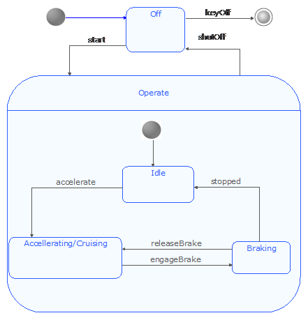
Example
The following example is extracted from the SysML 1.2 specification and implemented in the SysML Architect module.