UML tool: Deployment diagrams
Examples of UML deployment diagrams with Modelio
UML2 deployment diagrams are used to represent physical architecture of a system using nodes and connections between these nodes.
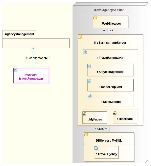
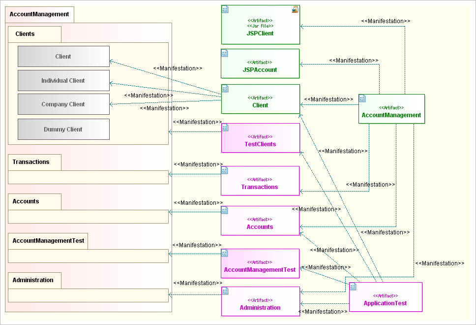
UML2 artifacts are used to define the configuration of elements produced from models. They appear as orthogonal model elements, and enable the definition of source files, binaries, libraries, DB schemas and so on, by designating the model elements from which they are composed (through "manifest" links). Modelio uses artifacts to specify the automated production of makefiles or ANT files.
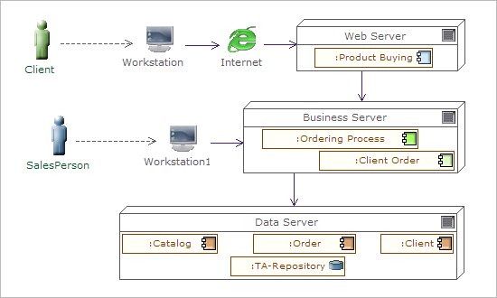
The example of UML2 deployment diagram on the right shows how logical applications identified during Enterprise Architecture modeling are deployed on hardware.
The Modelio TOGAF Architect module is used to model servers, workstations, networks and network nodes. The combined use of UML nodes and the internal structure of nodes (see UML class diagrams) enables us to illustrate this projection from a model (representing a service-based application and assembling service components) onto a physical target (servers, workstations, etc.).
The example here shows the use of nodes and artifacts to represent how different architectural element are distributed, deployed and connected. The connectors (links) between nodes or node instances represent network connections with specific protocols.